SRM-CAM
Desktop CAM for the Roland SRM-20: load KiCad Gerber + Excellon files, walk the run plan, and export ready-to-run G-code — with a probed surface the cut follows, several boards on one sheet, and double-sided registration built in.
Windows installer
Linux AppImage
G-code (.nc) & RML output
Open source
How it works
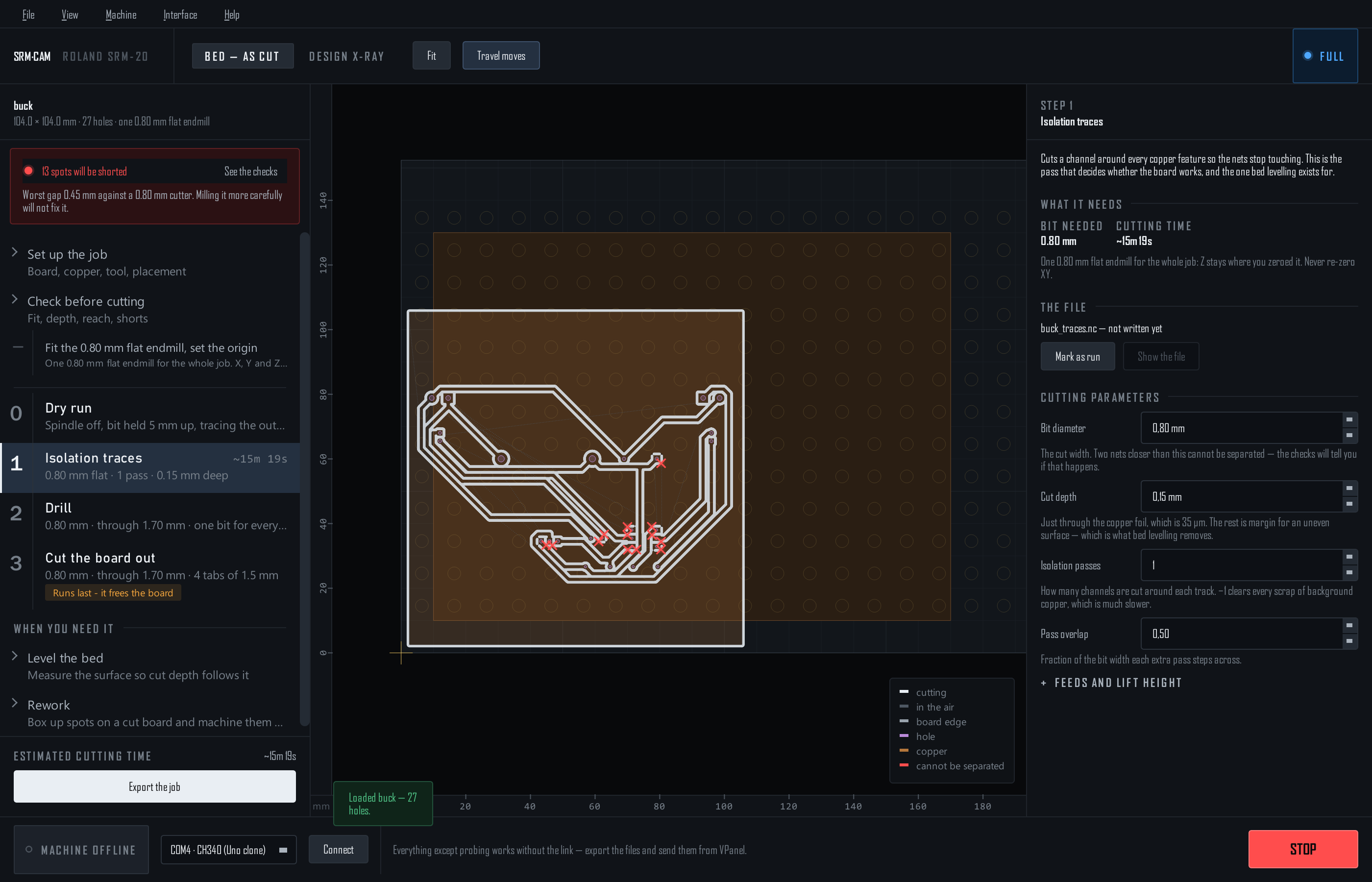
One program for the whole SRM-20 flow. Every step of the run plan is a file you send from VPanel — traces, drill, cut-out — and step 0 is a spindle-off dry run that traces where the board will be cut before anything touches copper.
KiCad Gerbers→
SRM-CAM→
.nc files + run sheet→
VPanel→
Milled board
With the Arduino fitted, SRM-CAM also reads the machine's position, jogs, probes the bed and zeroes Z — VPanel still plays the files and sets the spindle speed. Machine control →
Guide contents
🚀Getting started
Install on Windows or Linux, learn the four regions of the window, the two tiers, and the files KiCad has to give you.
🛠️Milling a board
Set up, check, export, run: the single-sided workflow from a Gerber folder to a board, with the run sheet at the end.
🧩Several boards on one sheet
Two or more designs on one piece of copper, cut in one run — one cut between boards that touch, none along the sheet's edge.
🔩Holding the copper
Screws through the spoilboard grid, a datum the machine drills itself, the dry run, and what a board held at points does to the cut depth.
📐Bed levelling & probing
Probe a height map over the link — or by hand — and every cut follows the real surface. One map per face.
🔁Double-sided boards
Dowel-pin or fiducial registration, the flip, measuring where the board landed, and the top files re-written to match.
📷Photo check & rework
Lay a photo of the board on the bed, box the spots that did not cut, and re-cut them deeper in one program.
🔌Hardware & firmware
The Arduino on the machine's SPI bus: wiring, one-command flashing, how a touch is measured, and the safety limits.
🎛️Machine control
The machine bar and menu: position, jog, zero Z, spindle, STOP — and an honest list of what the link cannot do.
📄Files & reference
Every file SRM-CAM reads and writes, setups, tool profiles, the parameters, the command line and the keys.
🩹Troubleshooting
Symptom → fix, learned on real boards: depth, reach, probing, registration, setups.
Highlights
- The checks are on screen, not in a box. Fits the bed, Z reach from the probed surface, nets the bit cannot separate (marked on the traces), the job on the copper, the screws in reach — all the time, and the worst finding stays on the rail until it is fixed.
- Depth you can trust. Probe the surface electrically and the cut follows it, per face. A board held at points gets a small, capped extra depth for the give under the cutter, and you can set it yourself.
- Several boards, one run. Put two designs on one sheet; touching boards share one cut, and an edge on the sheet's edge is not cut at all.
- Double-sided that registers. Dowel pins (sub-0.1 mm, nothing to measure) or fiducial holes found electrically after the flip, with the top files re-written to where the board actually landed.
- STOP is part of the window. Never hidden by a tier, a step or a dialog; Esc does the same from anywhere.
- A run sheet, not a text file. Export writes the files and puts the plan in front of you: order, bit, depth, time, and the one rule — never re-zero XY.
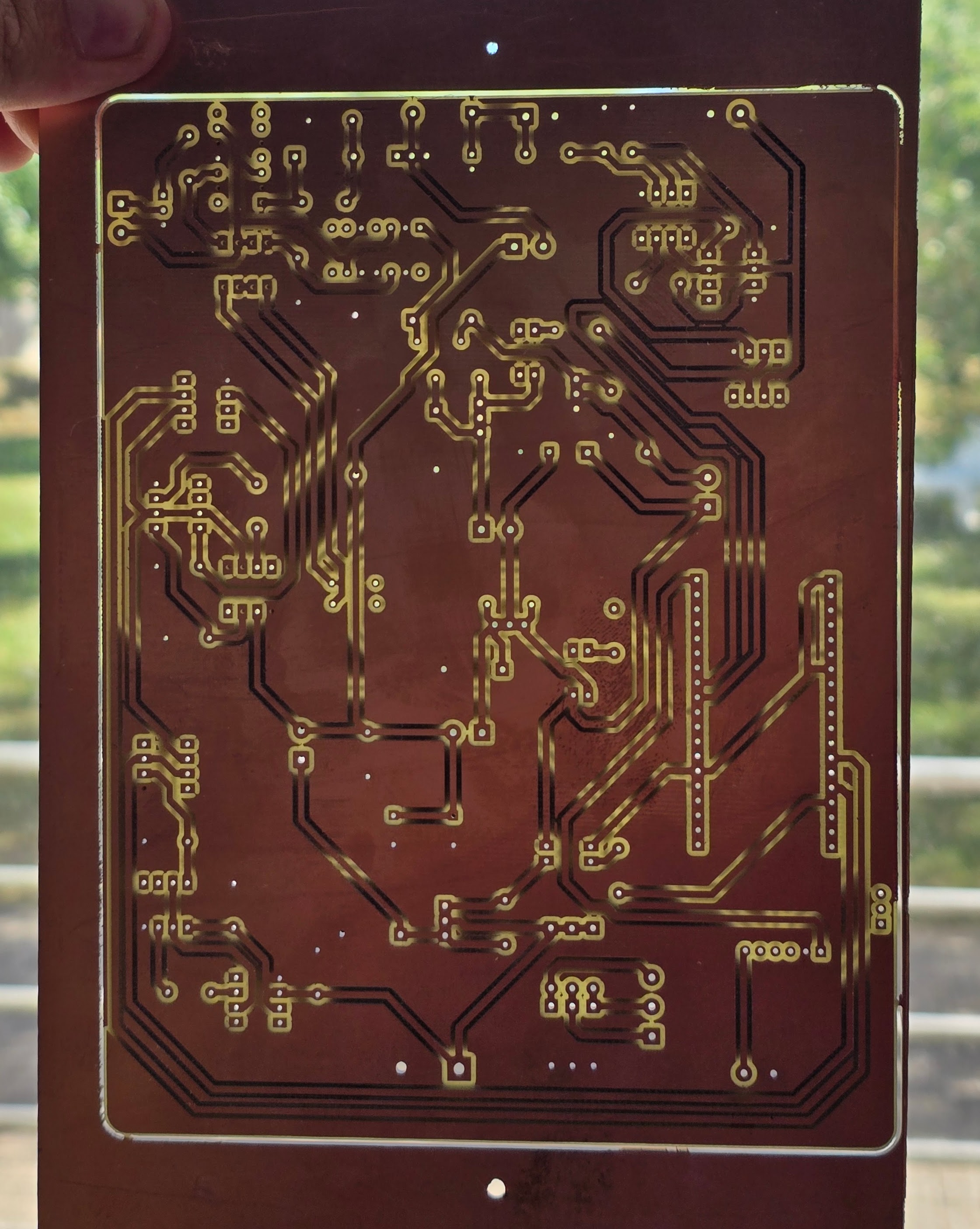
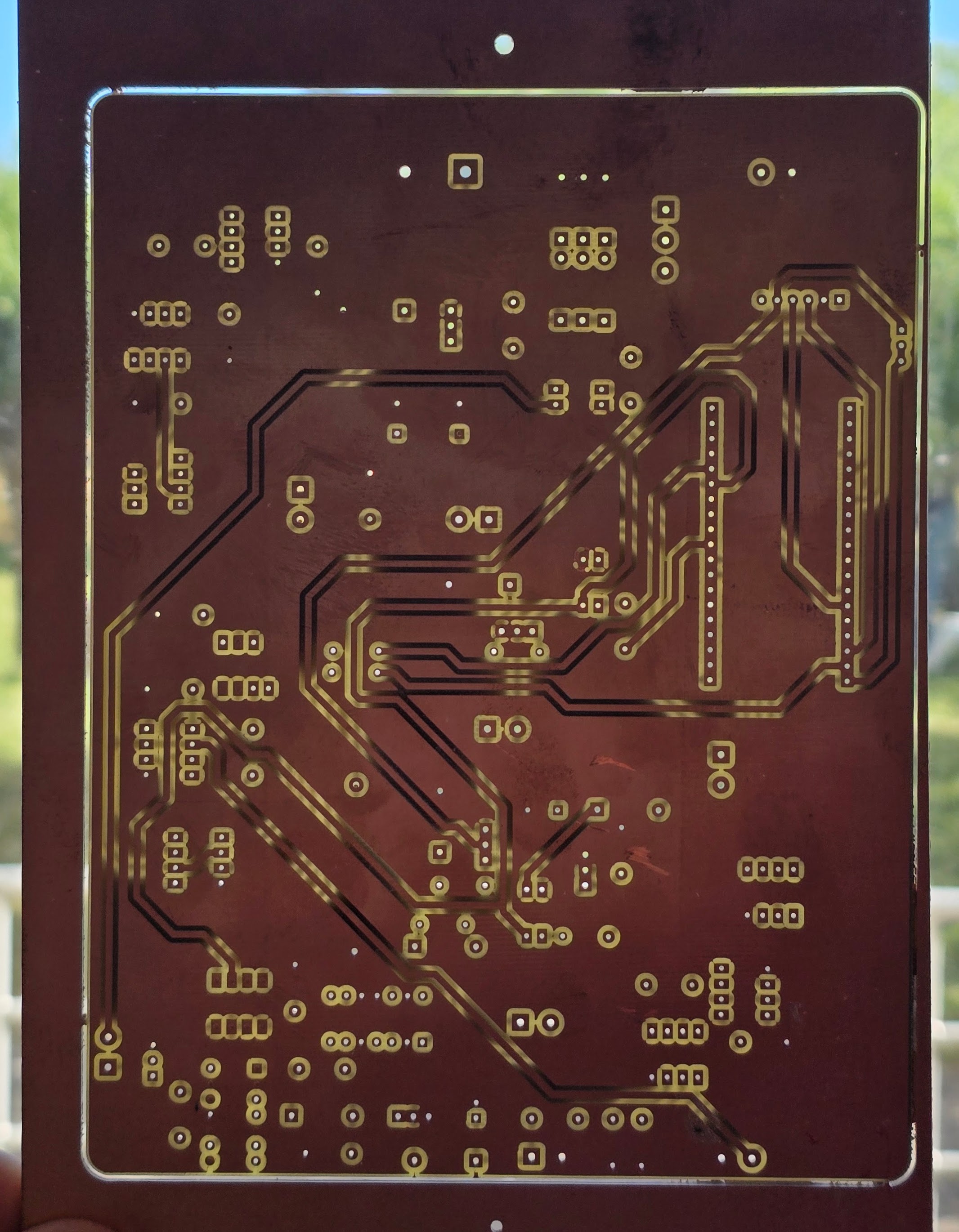
A finished board
Both sides of a double-sided board milled with SRM-CAM, registered off dowel pins, held to the light: