Holding the copper
Almost every ruined board comes down to one question: does the machine know where the copper is, and will it still be there in ten minutes?
1 · Bolt it down through the spoilboard
The spoilboard has a grid of M4 threads on a 10 mm pitch. On the setup page tick Held down with M4 screws: SRM-CAM picks the grid holes your sheet covers that land clear of the design, and Write the screw file… writes <name>_screws.nc — clearance holes through the copper only — with the procedure beside it. Choose the screw holes myself lets you click the holes on the bed instead.
Run that file first, drop an M4 screw through each hole and tighten into the plate — snug, not hard. Re-zero Z afterwards; the board pulls down as you tighten.
Screw heads stand about 3 mm above the copper and the default lift between cuts is 2 mm. Ticking the box raises the lift to 4 mm on all three operations, and only ever raises it. The checks then watch the lift against the heads, and whether four usable holes exist.
The grid is modelled from a measured position on the machine, and the file is written at those absolute coordinates. It only lands on the threads if the XY work origin is the machine origin — the standing rule here: zero only Z, leave X and Y at the machine origin.
2 · A board held at points bows
Screwed or clamped, the board can arch over air between the fixings. The probe measures that arch with a static tool at almost no force; the cutter arrives spinning and pushing down, and the unsupported part gives a little instead of being cut. Held down by on the setup page says how the copper is held:
- Screwed or clamped at points — the cut is deepened by a quarter of the arch the probe map shows, plus the copper foil, capped at 0.12 mm. The number is on the page; untick Work the extra depth out from the probe map to set Cut deeper by yourself, down to nothing, if the board keeps coming out too deep or too shallow.
- Bonded across the whole back (tape) — there is nowhere for it to go; nothing is added. It is the better fixture.
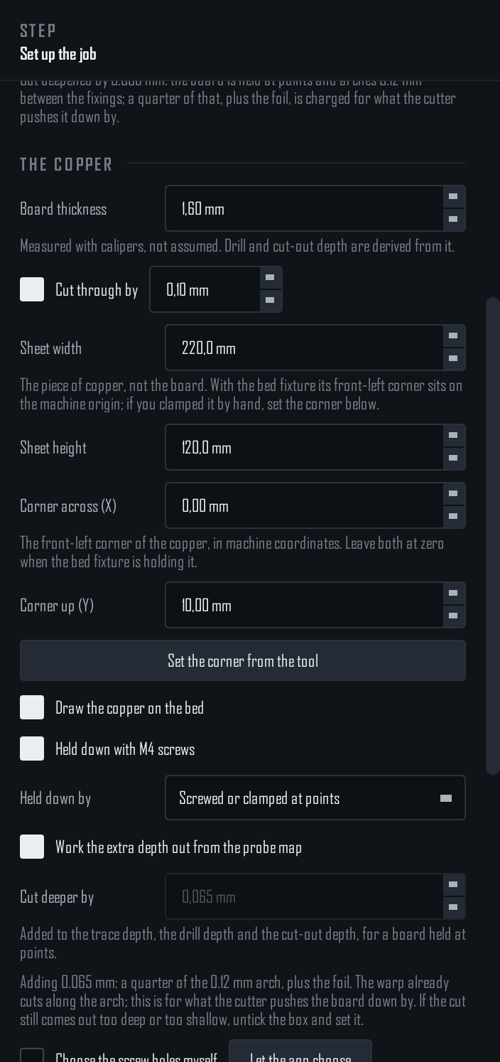
The warp cuts along the arch already; this only covers the give under the cutter. A board that arches more than the cap wants re-fixing, not a deeper cut. And the map has to be applied — with the warp off, nothing cancels the tilt, and the whole range is charged.
3 · Let the machine drill its own datum
Machine → Export the bed fixture (pin holes)… writes a job that drills three dowel-pin holes into the spoilboard, named after the stock size because the fixture is per-bed. Press pins in, push the stock up against them, and its front-left corner lands on the work origin every time.
4 · Prove it before you cut
Every single-sided export writes <name>_airpass.nc, step 0 of the plan: spindle off, bit held 5 mm up, tracing the outline slowly enough to follow. If it wanders off the copper, stop and re-place the stock. Twenty seconds, before every job.
Which one do I need?
| Situation | Use |
|---|---|
| One board, tape is holding fine | The dry run alone; Held down by bonded |
| Deep cut-out, thin stock, or the board chatters | Screws — and probe the bed, so the extra depth is measured rather than guessed |
| Repeating the same stock size often | Bed fixture, set up once |
| Double-sided | Dowel registration — see Double-sided boards |